Safety Notice
To avoid accident or damage, please be sure to read the Safety Notice carefully before use of the pump.
Be sure to follow the safety instructions in this section. The Operating Instructions is very important and may prevent the pump operator or other people from injury or mitigate property damage.
1.Safety Warnings
1)Hazard of magnetic field: The pump driven by magnetic force will generate a very powerful magnetic field that will cause adverse impact to those who wear electronic medical devices (e.g. electronic pacemaker).
2)Be sure to cut off the power supply before repair or other work. When there is someone repairing the pump, take protective measures to prevent other operators from switching on the power supply by mistake. In noisy or dark environment, place a clear sign beside the power switch to warn others. Switching on the power supply by mistake during maintenance may cause severe accident or even human death. Every person shall take special care.
3)Please wear safety goggles, protective gloves, protective clothes and other necessary protective equipment when replacing the pipe system or removing or assembling the pump.
4)When lifting the pump, use chain or belt to pass through the lug or motor to keep the pump and motor on level position. Do not stand beneath the lifted pump.
5)To avoid leakage, be sure to perform routine inspection and maintenance of the pump when it is used for trans porting the following dangerous liquids. In the event of leakage, such dangerous liquids (or volatile gas) will cause human death, explosion or fire.
a)Inflammable or explosive liquids;
b)Corrosive or poisonous liquids;
c)Liquids harmful to human body.
2.Safety Cautions
1)The magnetic pump will generate powerful magnetic field. Take care to prevent the strong magnetic force from causing harm to human body (e.g. squeezing your fingers, interference to pacemaker, etc).
2)Avoid idle run: Idle run may heat and expend the bearing to lock the axle, thus resulting in damage to the pump. (It is also deemed idle run if the pump works with the inlet and outlet valve closed).
3)The pump maintenance personnel shall have professional knowledge and operating
experiences.
4)Magnetic pump made of special materials shall be used for designated working conditions only; otherwise the normal performance and service life of the pump cannot be guaranteed, or even accident may be caused.
5)Requirements for site ventilation: If the pump is used for transporting the volatile poisonous gas, safety measures, e.g. ventilation equipment, must be taken to avoid liquid leakage in case of emergency.
6)Avoid liquid leakage: To prevent the liquid from flowing directly into the ground, protective measures shall be taken against the leakage caused by emergency accident or pipe damage.
7)Select the electromagnetic switch according to motor specification, e.g. rated voltage and rated power.
8)If the pump is installed outdoor, protective measures must be taken for the electric circuits, thus to prevent the water from flowing into the switch.
9)The electromagnetic switch and buttons shall be installed correctly and away from the pump.
Introduction
1.Use and Features
This pump is widely used in such industries as petrochemicals, acid / alkali making, non-ferrous smelting, acid wash in automobile manufacturing, rare earth separation, pesticides, dyes, pharmaceuticals, papermaking, electro-plating and radio. It is suitable for transporting clear liquids or corrosive medium containing tiny particles (solid content≤10%).
Features: External mixture structure, stable in self-priming function, and no need for installation of bottom valve. Before use for the first time, it is needed to fill the pump with the liquids to be transported; but it is not needed for the second time of use. The flow passage components are manufactured of fluorine plastic alloy, so that the pump may transport the corrosive liquids of any concentration such as acid, alkali and strong oxidants.
2.Packaging and Inspection
Check the following after unpacking:
1)If the pump and its accessories (including the other documents required by the user) are
complete as on the Packing List.
2)If the data on the nameplate of the pump and motor are according to the order requirements.
If the pump is damaged during transport and if the bolts are loose.
3.Model Definition
80 FZB-30L
80: Pump inlet diameter 80mm B: Single-step single-suction centrifugal pump
F: Made of fluorine plastic 30: Pump head 30m
Z: Self-priming function L: Long support
Notes:
1)Motor step: 2-step
2)If the specific gravity of the liquid exceeds 1.3g/cm3, the user is suggested to add the motor power of as appropriate.
3)If the liquid contains HF acid or some special medium, it is needed to replace with special components according to the liquid properties.
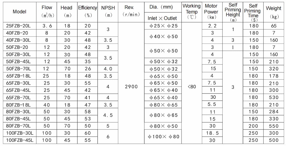
4)Allowable self-priming height may be calculated as per: Sell-priming of clear water for 3m / liquid density = self priming height
5.Scope of Application
1)Pressure limit: The pressure limit is 1.6MPa. Take care that the output pressure of the pump shall not exceed the pressure limit.
2)Working temperature: -20~<100℃; Variance of ambient temperature: 0~40℃; Variance of ambient humidity: 35~85%RH
3)Never use the pump for transporting the medium that contains tiny particles and crystals. Never use the pump for transporting the medium that may generate plentiful bubbles.
4)Impact of liquid viscosity to the pump performance: The pump performance varies with the
liquid viscosity.
6.Structure and Parts Name
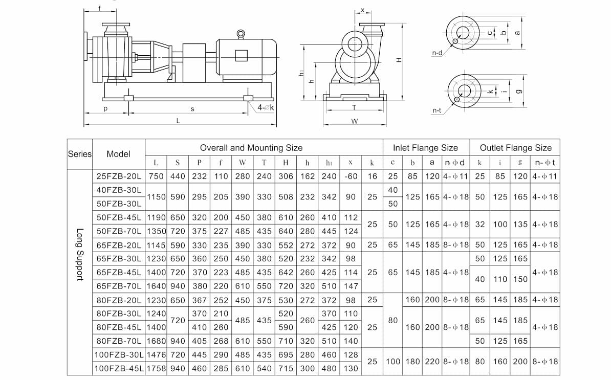
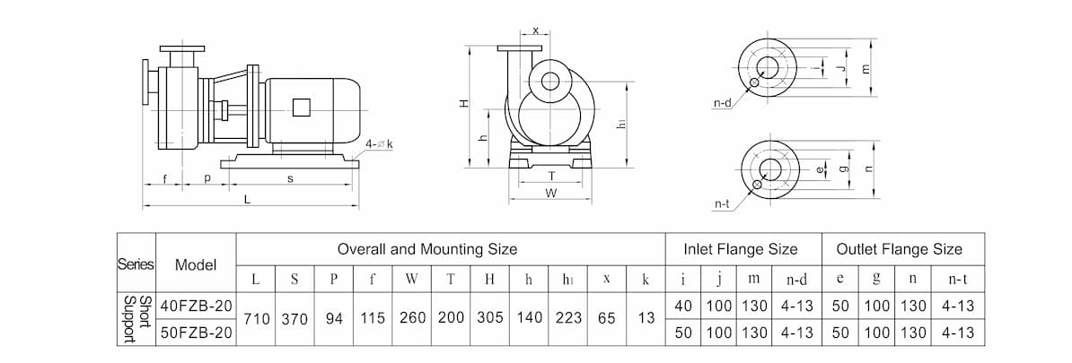
7.Mounting Size

1.Key Points of Installation
1)The pump shall be installed and fixed on solid foundation free from the impact of mechanical vibrations.
2)The foundation shall weigh three (3) times the equipment or higher, and be larger than the seat.
3)For easy repair and maintenance, adequate space shall be left around the pump.
4)Place the pump unit on the foundation. Gaskets shall be paved between the seat and foundation.
2.Pipe
1)The pipes into and out of the pump shall be supported. Do not use the pump as the support. The pipe diameter shall be compatible to the pump inlet / outlet size.
2)Ensure that the mounting height of the pump conforms to the NPSH. The pipe loss and medium temperature shall be also considered. To avoid generation of NPSH within pump body, be sure to follow the formula below:
NPSHa ≥ NPSHr + 0.5, in which:
NPSHa: Effective (equipment) NPSH (m) NPSHr: Necessary (pump) NPSH (m)
3)The pipe bend shall be as smooth as possible. Minimize the bends and avoid bend at the position close to the pump inlet. Use the shortest pipe as might be.
4)Do not use the protruded pipe or inverted U-pipe. The inlet pipe shall be connected upward per 1/100 gradient.
5)If the pump inlet diameter differs from outer diameter, please use eccentric reducing pipe and make the upper part level. (If connected in reverse, it is possible that the gas inside the pipe cannot be discharged). The liquid drop shall be considered. The suction pipe shall be positioned at an adequate immersed depth. To prevent the foreign particles from entering the pump, filter shall be installed at the inlet. The filtration area shall be 3-4 times larger than the section area of the pipe. The filter shall be cleaned regularly.
6)The outlet pipe must be installed with a valve for regulating the flow and making the pump work at the specified flow, so as to avoid malfunction of the pump due to overflow. A check valve shall be installed to avoid damage by surge when the pump is stopped. The correct sequence of installation shall be as pump check valve gate valve.
7)The pipe must be correctly connected. The sealing gasket between the flanges shall be smooth and not be mal-positioned. If there is leakage on the seal, the pump cannot work normally or the pump might be even damaged.
Operation and Maintenance
1)Always avoid idle run of the self-priming pump. The minimum flow of the pump during operation shall be 35% of the design value.
2)If cavitations occur when the pump is running, be sure to stop the pump within one (1) minute.
3)The variance of medium temperature shall be controlled within 40℃. If the temperature rise / drop are too high, it might cause damage to the pump components.
4)If there is sudden power failure when the pump is running, be sure to cut off the power supply immediately and close the outlet valve.
5)The pump noise is ≤85dB. If there is vibration or noise, please stop the pump and check it. Do not restart the pump until the trouble is eliminated.
6)For the self-priming pump where the bearing is lubricated by grease, never add machinery oil into the bearing box additionally.
2.Start and Operation
1)Start
Calibrate the coupler before starting the pump.
(1)Before calibrating the coupler, control the rotating direction of the motor at the disengagement position according to the arrow on the pump.
(2)The flexible coupler requires careful calibration of its axis. Adjusting gasket may be used for adjustment. Any negligence during calibration may cause damage to the coupler, pump and drive bearing.
(3)To calibrate the coupler, a precision ruler may be placed against the outer edge of the coupler to observe its parallelism to the axis from several points. A feeler gauge may be used on several positions to control the distance between two semi-couplers.
2)Operation
(1)Fill the pump with the liquids to be transported. After completing the pipe installation, connect the power supply and open the outlet valve for approx. 1/3; then you can start the pump (that is, open the valve to start the pump). Wait until the self-priming process is ended; then, slowly adjust the outlet valve to make the pump reach the specified flow.
(2)Test run the pump for 5 – 10 minutes. If there is no abnormality, put the pump into normal operation.
(3)During transport of the liquids, the flow, head and self-priming height must be controlled within specified range and shall not vary largely; otherwise air suction may be caused, resulting in that the pump cannot work normally.
(4)Air suction is not allowed when the pump is working. In case of air suction, the pump must be discharged and refilled with liquids before it can perform self-priming function. Therefore, the user must provide the equipment that can control the lowest liquid level, and designate special person to watch it, thus to prevent the liquids within the tank from being emptied.
(5)To stop the pump, firstly close the outlet valve and then disconnect the power supply.
3.Repair and Maintenance
1)Check the pump and motor regularly. Replace the easily-damageable components.
2)If the pump is stopped and placed long out of service, the flow passage inside the pump shall be flushed and the power supply shall be disconnected.
3)Always avoid idle run. If the pump is installed outdoor, rainproof measures shall be taken to prevent the motor from burn due to moisture.
4.Removal and Assembly
The removal procedures are as follows. The assembly procedures are in reverse.
1)For Model FZB, the motor is directly coupled. During removal, firstly remove the motor housing and loosen the tension bolts. Then, use the wood to knock the screws at the tail of motor shaft. Finally, disengage the impeller and pump cover.
2)Model FZB-L is of long-support structure. Removal: ① Loosen the bolts fixing the motor to the seat, and separate the motor from pump head; ② Loosen the bolts fixing the suspension support to the seat, and the bolts fixing the pump body to the support. Then, separate the impeller, pump cover and support from the pump body and motor; ③ Loosen the tension bolts at the tail of support, and knock with wood to disengage the impeller and pump cover.
3)Loosen the screws tightening the dynamic ring of mechanical seal and remove the dynamic ring. Loosen the seal gland on pump cover and remove the static ring.
4)Loosen the bearing glands on two ends of the bearing box, and remove the pump shaft and bearing.
Loosen the bolts fixing the pump body and front cove; then separate them. Loosen the bolts fixing the pump body and outlet flange; then separate them
5.Service Commitment
1)Long-term supply is ensured for the easily-damageable parts and other components.
2)New model of corrosion-resistant pump and explosion-proof motor may be designed according to the user requirements.
3)We provide technical supports and life-long services for our products.
4)We provide door-to-door commissioning and repair free of charge (The easily-damageable parts are charged per the ex-works price).
6. Troubleshooting
|
Fault
|
Cause
|
Solution
|
|
No liquid pumped
|
1. There is air in the suction pipe.
2. The suction pipe leaks air.
3.The liquid filled into the pump is insufficient.
4.The suction pipe is blocked by foreign substances.
5. The pump rotates in wrong direction.
6. The suction height is too high.
|
1. Refill liquid or exhaust the air.
2. Check the suction pipe.
3.Refill liquid.
4.Clear off the foreign substances.
5. Adjust the rotating direction of the pump.
6. Reduce the mounting height of the pump.
|
|
The flow is low
|
1. Impeller is damaged.
2. The rotating speed is low.
3. The pipe is blocked by foreign substances.
|
1. Replace the impeller.
2. Check the motor and electric circuit.
3. Clear off the foreign substances.
|
|
The power is too high
|
1. The specific gravity of the medium is too high.
2. Mechanical friction exists.
|
1. Replace with the motor or pump that has a higher power.
2. Check the position of friction and make repair.
|
|
Pump head is low
|
1. There is air in the medium transported.
2. Impeller is damaged.
3. The rotating speed is low.
4. The viscosity of transported medium is too high.
|
1. Refill liquids or exhaust the air.
2. Replace the impeller.
3. Check the motor and electric circuit.
4. Reduce the viscosity or add the filling pressure.
|
|
The pump has vibration
|
1. The suction height is too high, thus generating cavitations.
2. Mechanical friction exists.
|
1. Reduce the mounting height or replace with self-suction pump.
2. Check the position of friction and make repair.
|
We also supply:
IH Series Stainless Steel Centrifugal Pump QBF Series Pneumatic Diaphragm Pump
CQ Series Stainless Steel Magnetic Pump FSB Series Fluorine Plastic Alloy Centrifugal Pump
IMD Series Fluorine Plastic Alloy Magnetic Pump FSB (D) Series Fluorine Plastic Alloy Centrifugal Pump
ZMD Series Self-suction Magnetic Pump CQB Series Fluorine Plastic Alloy Magnetic Pump
IHF Series Fluorine Plastic Alloy Centrifugal Pump FYH Series Fluorine Plastic Submerged Pump
IHF (D) Series Fluorine Plastic Alloy Centrifugal Pump
Different fluorine interlined valves, sight glass, pipes and fittings
UHB-ZK Series Mortar Pump
MFY-I Series Wear and Corrosion Resistant Pump
GF Series Fluorine Interlined Pipe Pump
 English


 Network Supported