Safety Notice
To avoid accident or damage, please be sure to read the Safety Notice carefully before use of the pump. Be sure to follow the safety instructions in this section. The Operating Instructions is very important and may prevent the pump operator or other people from injury or mitigate property damage.
1.Safety Warnings
1)Be sure to cut off the power supply before repair or other work. When there is someone repairing the pump, take protective measures to prevent other operators from switching on the power supply by mistake. In noisy or dark environment, place a clear sign beside the power switch to warn others. Switching on the power supply by mistake during maintenance may cause severe accident or even human death. Every person shall take special care.
2)Please wear safety goggles, protective gloves, protective clothes and other necessary protective equipment when replacing the pipe system or removing or assembling the pump.
3)When lifting the pump, use chain or belt to pass through the lug or motor to keep the pump and motor on level position. Do not stand beneath the lifted pump.
4)To avoid leakage, be sure to perform routine inspection and maintenance of the pump when it is used for transporting the following dangerous liquids. In the event of leakage, such dangerous liquids (or volatile gas) will cause explosion, hazard or human injury.
a)Inflammable or explosive liquids;
b)Corrosive or poisonous liquids;
c)Liquids harmful to human body.
2.Safety Cautions
1)Avoid idle run: Idle run may heat impeller axle and destroy the mechanical seal due to dry friction, thus resulting in damage to the pump. (It is also deemed idle run if the pump works with the inlet and outlet valve closed).
2)Avoid damage due to static charge: Static charges will be generated if the pump is uses for transporting the liquids of low conductivity, e.g. ultra-pure water or fluorine-contained inert fluids. This will cause electric discharge and damage to the pump. Measures shall be taken to prevent the generation of static charges or other measures shall be taken to lead the static charges.
3)The pump maintenance personnel shall have professional knowledge and operating experiences.
4)Centrifugal pump made of special materials shall be used for designated working conditions only; otherwise there is no way to ensure the normal performance and service life of the pump, or it may even cause accident.
5)Requirements for site ventilation: Safety measures must be taken if the pump is used for transporting the volatile poisonous gas. For example, ventilation equipment may be installed to avoid liquid leakage in case of emergency.
6)Avoid liquid leakage: To prevent the liquid from flowing directly into the ground, protective measures shall be taken against the leakage caused by emergency accident or pipe damage.
7)Select the electromagnetic switch according to the motor specification, e.g. rated voltage and rated power.
8)If the pump is installed outdoor, protective measures must be taken for the electric circuits, thus to prevent the water from flowing into the switch.
9)The electromagnetic switch and buttons shall be installed safely and away from the pump.
Introduction
1.Use and Features
Use:
This product is widely used in industries such as petrochemicals, acid and alkali production, non-ferrous metal smelting, acid washing processes in automobile manufacturing, rare earth separation, pesticides, dyes, pharmaceuticals, papermaking, electroplating, radio, etc. It is suitable for transporting clear liquids or corrosive media containing small amounts of particles.
Features: External hybrid structure, stable and reliable self-priming performance, no need to install a bottom valve. When first used, the pump chamber needs to be filled with conveying medium, and there is no need to add medium for secondary use. The overcurrent components are made of stainless steel and the material of the overcurrent components can be changed according to the medium being transported.
2.Packaging and Inspection
After opening the packaging box and bag, please check the following items:
(1) Whether the product, accessories (including other information requested by the user) match and are complete with the packing list;
(2) Check the various data on the nameplates of the pump and motor to confirm whether they meet the ordering requirements;
(3) Is there any damage to the product during transportation, and are there any loose connecting bolts.
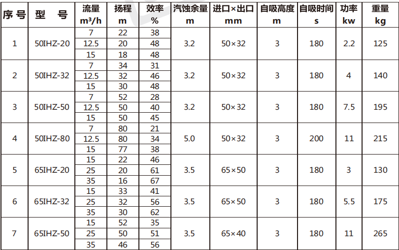
3.Model Definition
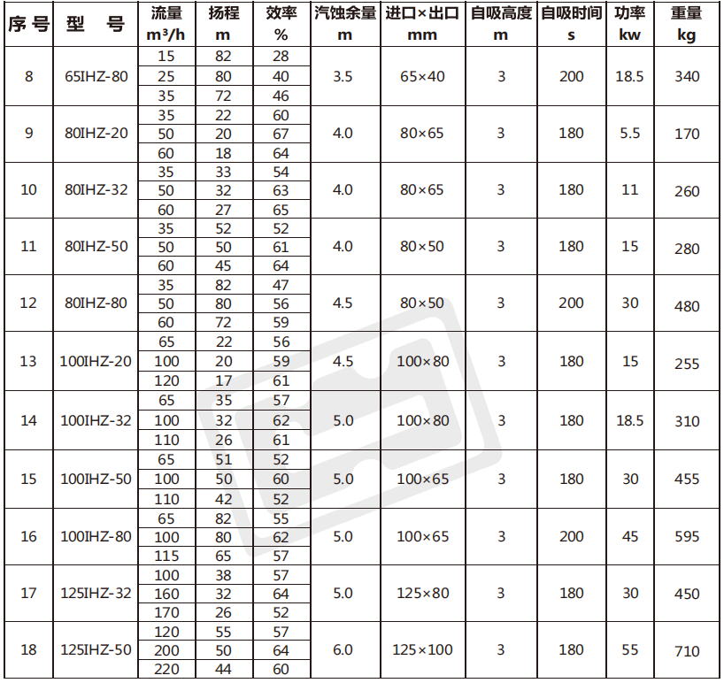
80 IHZ - 32
80: Pump inlet diameter 80mm IH: International standard chemical pump series code
Z: Self priming pump 32: The lift is 32m
Notes:
1. Motor level: 2 levels.
2.When the medium has a specific gravity, it is recommended that customers increase the power of the supporting motor appropriately.
3.When the conveyed medium contains some special components, specific accessories must be replaced according to the specific medium.
4. The allowed self-priming height can be calculated according to the formula: 3m self-priming in clear water/medium density=self-priming height.
5.Scope of Application
1. Pressure resistance limit: The pressure resistance limit is 1.6MPa, and it should be noted that the output pressure of the pump cannot exceed the pressure resistance limit.
2. Temperature range for use: -0~150 ℃; Range of environmental temperature variation: 0-40 ℃; Range of environmental humidity variation: 35-85% RH.
3. It can transport media with small particle content and crystallization, and it is forbidden to transport media that will generate a large number of bubbles.
4. The influence of liquid viscosity on pump performance: When the viscosity of the liquid changes, the performance of the pump also changes.
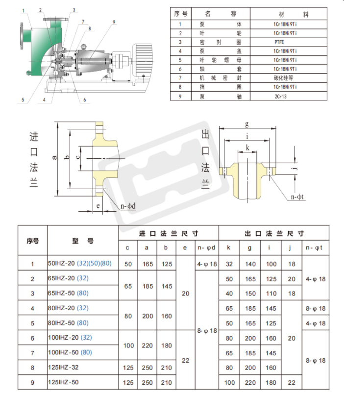
6.Structure and Parts Name
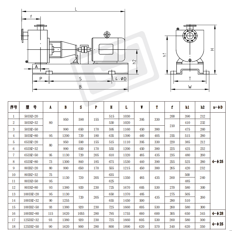
7.Mounting Size
1.Pump Foundation
1、 Installation points
1. The pump should be installed and fixed on a stable foundation, unaffected by other mechanical vibrations.
2. The weight of the foundation itself must be more than three times the mechanical weight, and the area must be larger than the base.
3. Adequate space should be reserved around the pump for maintenance and repair.
4. Place the pump unit on the foundation, and a cushion should be laid between the base and the foundation.
2、 Pipeline
1. The inlet and outlet pipelines of the pump should have brackets and cannot be supported by the pump. The diameter of the pipeline should be consistent with that of the pump. The pump should be located as close as possible to the water tank.
2. It is necessary to ensure that the installation height of the pump meets the cavitation allowance of the pump, and to consider pipeline losses and medium temperature. To avoid cavitation inside the pump body, the following equation must be met:
NPSHa≥NPSHr+0.5
NPSHa: Effective (device) cavitation allowance (m)
NPSHr: Required (pump) cavitation allowance (m)
3. The curved part of the pipeline should be as smooth as possible to reduce the use of bends, and avoid setting bends near the pump inlet.
4. The diameter of the inlet pipe shall not exceed the specified requirements, and the total length shall be less than 5m. The shorter, the better, provided that the requirements are met. Considering the descent of the liquid level, the position of the suction pipe should have sufficient submergence depth. To prevent debris from entering the pump, a filter should be installed at the inlet with a filtration area greater than 3-4 times the cross-sectional area of the pipeline. And clean the filter regularly.
5. The diameter of the outlet pipe shall not be less than the specified requirements. If possible, the larger the pipe diameter, the better, and the total length must be greater than the inlet
1.5 times the total length of the liquid tube, if possible, it would be better to extend it a little longer. Valves must be installed in the outlet pipeline to regulate the flow rate and ensure that the pump operates at the specified flow point, preventing the pump from malfunctioning due to excessive flow.
6. When the pump is used in an environment below the liquid level or as a substitute for a pipeline pump, air valves and buffer valves cannot be used. In this case, please remove the valves.
7. Check valves shall not be installed in the pump outlet pipeline. If any, a vent hole shall be provided at the lower end of the check valve.
8. When installing pipelines, connect the inlet pipe first, fill it with liquid, and then connect the outlet pipe. The pipeline must be connected correctly, and the sealing gasket between the flanges must be flat and not misaligned. If the sealing surface leaks, the pump will not function properly and may cause damage to the pump.
一、 Precautions before use
It is strictly prohibited to control the flow by closing or adjusting the inlet valve to avoid damage to the impeller and other components
1. Self priming pumps are prohibited from running without air, and the minimum flow rate during pump operation is 35% of the design point.
2. If cavitation occurs during pump operation, it must be stopped within 1 minute.
3. The temperature change of the medium should be controlled within 40 ℃, as excessive temperature rise/fall may cause damage to pump components.
4. If there is a sudden power outage while the pump is running, the power must be immediately turned off and the outlet valve must be closed.
5. The noise of the pump is ≤ 85dB. If vibration and noise are found, the machine should be stopped for inspection and troubleshooting before it can work.
6. For self-priming pumps that use grease lubricated bearings, it is prohibited to add additional oil to the bearing housing.
二、 Start and Run
(1) Start up
Before starting the pump, the coupling needs to be calibrated:
1. Before calibrating the coupling, control the rotation direction of the motor according to the direction of the steering arrow on the pump at the separated position;
2. Elastic couplings require careful calibration of the axis line, which can be adjusted using shims. Carelessness during calibration can result in damage to the coupling, as well as damage to the pump and driver bearings;
3. For coupling calibration, a precise ruler can be used to observe the parallelism with the shaft at any point along the outer edge of the coupling, and a thick plug gauge can be used to control the distance between the two half couplings at several corresponding positions;
(2) Run
1. Fill the pump with the liquid to be transported, install the pipeline, connect the power supply, open the outlet valve about one-third, and start the pump (i.e. open the valve to start). After completing the self-priming process, slowly adjust the outlet valve to reach the specified flow range of the pump.
2. Test run the unit for 5-10 minutes, and if there are no abnormal phenomena, it can be put into operation.
3. During infusion, the flow rate, head, and self-priming height must be controlled within the specified range and cannot differ too much, otherwise it may cause suction and prevent the pump from working properly.
4. The pump is not allowed to produce suction during operation. Once suction occurs, it must be drained and refilled before it can self suction. Therefore, users must have a device to control the minimum liquid level or assign a dedicated person to supervise to prevent the liquid in the pool from being sucked out.
5. When shutting down, first close the outlet valve, and then cut off the power supply.
三、 Repair and maintenance
1. Regularly inspect the pump and motor, and replace vulnerable parts.
2. When the pump is not in use for a long time, the flow channel inside the pump should be cleaned and the power should be cut off.
3. Air freight transfer is strictly prohibited. If the pump is outdoors, rainproof measures should be taken to prevent the motor from being damaged by moisture.
四、 Disassembly and assembly
1. Close the inlet and outlet valves, loosen the motor foot bolts, and separate the motor from the pump head (i.e. motor coupling and pump coupling).
2. Remove the protective cover, loosen the connecting bolts between the bracket and the pump body, and the suspension bracket bolts to separate the impeller, pump cover, bracket, bearing box, and mechanical seal from the pump body.
Interior mounted single end face
① Loosen the impeller nut, remove the impeller lock nut, separate the impeller from the shaft, and remove the sealing gasket and anti rotation pin.
② Directly remove the pump cover assembly with mechanical seal, loosen the mechanical seal cover bolt, and remove the mechanical seal static ring.
③ Remove the shaft sleeve, loosen the two fastening screws of the mechanical seal dynamic ring, and the mechanical seal dynamic ring can be pushed out from the shaft sleeve.
④ If the pump body needs to be replaced, the connecting bolts of the inlet and outlet pipelines and the foot bolts of the pump body need to be removed.
Exterior style
① Loosen the impeller nut, remove the impeller lock nut, separate the impeller from the shaft, and remove the sealing gasket and anti rotation pin.
② Directly remove the pump cover assembly equipped with the mechanical seal static ring, loosen the mechanical seal cover bolt, and remove the mechanical seal static ring.
③ Remove the shaft sleeve, loosen the three fastening screws, remove the stop ring, loosen the two fastening screws of the mechanical seal dynamic ring, and remove the mechanical seal dynamic ring from the shaft sleeve.
④ If the pump body needs to be replaced, the connecting bolts of the inlet and outlet pipelines and the foot bolts of the pump body need to be removed.
Containerized double end face machine seal
① Loosen the impeller nut, remove the impeller lock nut, separate the impeller from the shaft, and remove the sealing gasket and anti rotation pin.
② Directly remove the pump cover assembly equipped with a mechanical seal static ring, loosen the bolt of the containerized double end mechanical seal cover, and remove the machine
Mechanical sealing static ring.
③ Loosen the set screws of the containerized double end face machine seal and remove the shaft sleeve from the machine seal.
④ If the pump body needs to be replaced, the connecting bolts of the inlet and outlet pipelines and the foot bolts of the pump body need to be removed.
五、 Service Commitment
1. Durable parts and other accessories ensure long-term supply.
2. New corrosion-resistant pumps and explosion-proof motors can be designed according to user requirements.
3. Provide technical consultation and lifelong service for the products provided by our company.
4. Responsible for free on-site debugging and maintenance (vulnerable parts are charged at the factory price).
6. Troubleshooting
|
Fault
|
Cause
|
Solution
|
|
No liquid pumped
|
1. The suction pipe leaks air.
2. The liquid filled into the pump is insufficient.
3. The suction pipe is blocked by foreign substances.
4. The pump rotates in wrong direction.
5. The self-priming height is too high.
|
1. Check the suction pipe.
2. Refill liquid.
3. Clear off the foreign substances.
4. Adjust the rotating direction of the pump.
5. Reduce the self-priming height.
|
|
|
1. The coupler is not concentric.
2. The elastic pad of coupler is worn.
3. The inlet pipe is too thin, or the inlet valve is not open.
4. The outlet valve is fully open.
5. The bearing is damaged.
|
1. Adjust the coupler concentricity.
2. Replace the elastic pad.
3. Replace the pipe and open the inlet valve.
4. Adjust the valve to rated condition.
5. Replace the bearing.
|
|
The flow is low
|
1. Impeller is damaged.
2. The seal is damaged.
3. The number of rotation is inadequate.
4. The pipe diameter is small.
5. Too many elbows on outlet pipe, resulting in that the resistance is too high.
|
1. Replace the impeller.
2. Replace the seal.
3. Increase the number of rotation. .
4. Reinstall the pipe according to specifications.
5. Rearrange the pipes as optimal.
|
|
The power is too high
|
1. The specific gravity of the medium is too high.
2. Mechanical friction exists.
|
1. Replace with the motor or pump that has a higher power.
2. Check the position of friction and make repair.
|
|
Pump head is low
|
1. There is air in the medium transported.
2. Impeller is damaged.
3. The rotating speed is low.
4. The viscosity of transported medium is too high.
|
1. Refill liquids or exhaust the air.
2. Replace the impeller.
3. Check the motor and electric circuit.
4. Reduce the viscosity or add the filling pressure.
|
|
The power is too high
|
1. The suction height is too high, thus generating cavitations.
2. Mechanical friction exists.
|
1. Reduce the mounting height or replace with self-suction pump.
2. Check the position of friction and make repair.
|
The seal is in severe leakage
|
1. The fluorine oil seal is damaged.
2. The fluorine oil seal is not concentric to the bushing.
3. The bushing is broken.
4. The components are not connected in parallel, resulting in that the fluorine oil seal is not concentric to the bushing.
|
1. Replace the fluorine oil seal.
2. Adjust the concentricity of the auxiliary oil seal and bushing.
3. Replace the bushing.
4. Adjust the parallelism during component
assembly; and adjust the concentricity of the
auxiliary oil seal and bushing.
|
|
|
1. The load is too high.
2. Motor bearing.
3. The clearance between couplers is too small.
|
1. Close the outlet valve smaller or replace with a more powerful motor.
2. Replace the motor bearing.
3. Adjust the clearance between couplers.
|
There is abnormal noise in the pump
and the pump has vibration
|
1. The pump shaft is not concentric to motor.
2. The flow exceeds the range.
3. The motor shaft is worn and the bearing is damaged.
4. The anchor bolt is loose.
5. The bearing hole of bearing box is not concentric.
|
1. Calibrate the center of pump shaft.
2. Select proper pump.
3. Wash or replace the bearing and pump shaft.
4. Tighten the anchor bolt.
5. Replace the bearing box.
|
We also supply:
CQB Series Fluorine Plastic Alloy Magnetic Pump
IMD Series Fluorine Plastic Alloy Magnetic Pump FSB Series Fluorine Plastic Alloy Centrifugal Pump
ZMD Series Self-suction Magnetic Pump FSB (D) Series Fluorine Plastic Alloy Centrifugal Pump
IHF Series Fluorine Plastic Alloy Centrifugal Pump FZB Series Fluorine Plastic Alloy Self-suction Pump
IHF (D) Series Fluorine Plastic Alloy Centrifugal Pump FYH Series Fluorine Plastic Alloy Submerged Pump
UHB-ZK Series Mortar Pump
Different fluorine interlined valves, sight glass, pipes and fittings
 English


 Network Supported